3d drawing of warm morning fire brick
Preface
In this affiliate will be shown what is actually done to create a complete space heater using the combustion cores introduced previously. The concepts will exist explained every bit we go, but non all of these volition necessarily have accompanying photographs if copyright restrictions are in place. But measurements and sketches could exist converted to 3D drawings in SketchUp format, by the builder of the heater or by me in due time. This way, sufficient information volition be available to people who like to build one or more of the designs for their own purposes.
The true magic of this engineering science is realised once we couple the clean burn technology of the combustion unit of measurement/s covered previously with effective ways of harvesting that very clean, smokeless heat. This tin can be done in a number of different ways that allow us to have unlike applications. Nosotros can build a infinite heater for applications that require 'estrus on demand', for example a workshop that is only occupied during working hours. This type has very little mass simply very high radiant output. For other cases (eg in a house) where long term 'constant heating' is needed we use much more mass that provides a lot of heat storage. These different approaches will be covered in this section.
All described variants are designed and/or built past Peter van den Berg, unless stated otherwise.
Only open source designs and descriptions will be included on this site, whether for people'south private use or commercially. The Creative Commons license Attribution and ShareAlike is allowed, the GPLv3 public license is also possible as an alternative, one-style compatible with the CC license mentioned here.
Workshop heater
Consisting of three oil barrels and a cast batch box rocket core. The core itself weighs 60 kg (132 lbs) just as the three steel oil barrels accept very little mass there is little delay to the rut output of the core, basically instant heat.
(read more)
Bell with two benches
This was built during a workshop so not as a permanent structure by a complete team in a little more than 3 days. A very interesting build, it showed outstanding performance.
(read more)
Bell heater, cast construction
A 2022 pattern and build of a heater which is entirely dry stacked out of cast parts.
(read more than)
Cardinal heating boiler
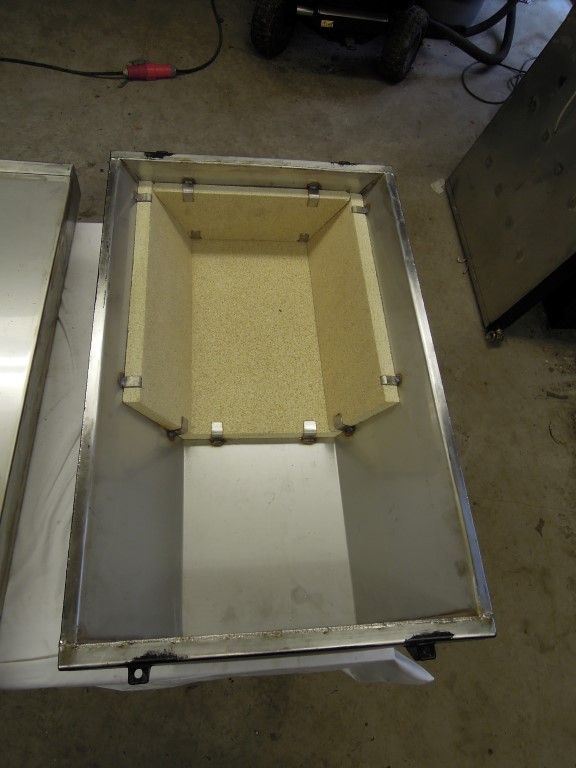
Also a design from 2015, the whole of information technology is fabricated of a lot of stainless steel, burn brick boards and split fire bricks. Information technology burns clean and hot, the unpressurized storage is heated up with it and in turn the in-floor heating is fed with warm water.
(read more)
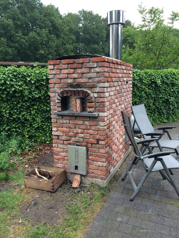
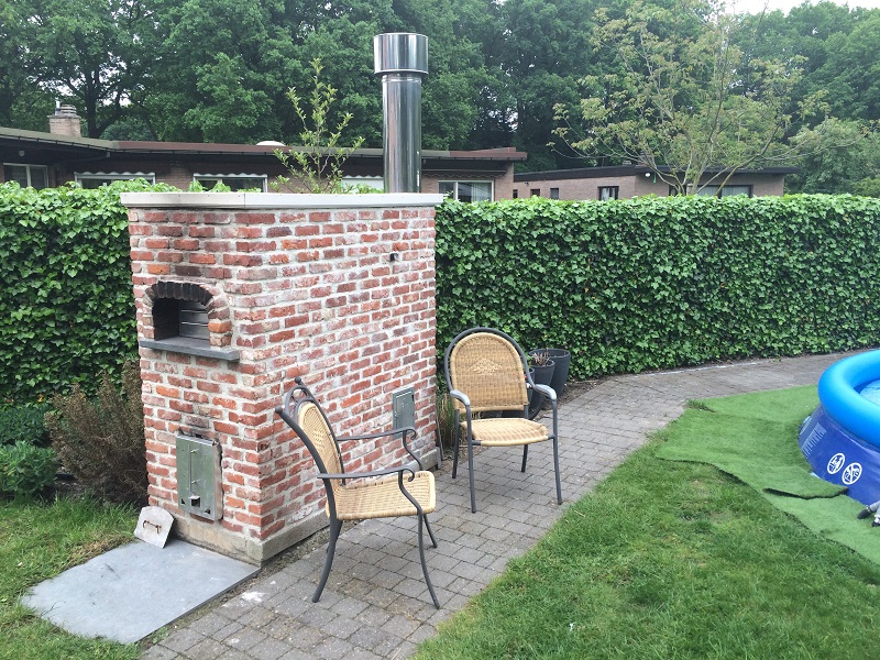
Pizza oven / pool heater
A third 2022 design, a batch rocket driving a pizza oven, warming the terrace and heating the swimming pool. Not for the fainthearted, merely a very rewarding build for Tom De Smedt.
(read more)
Open up batch rocket systems
These systems are built and run without a door or secondary air intake.
(read more)
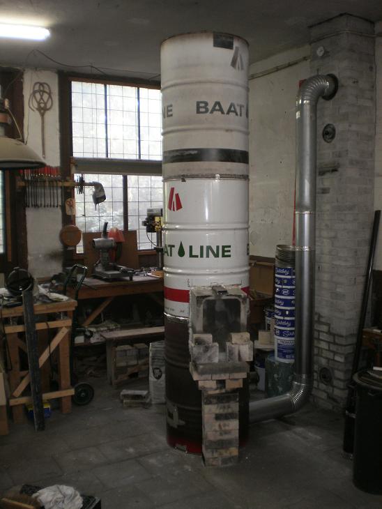
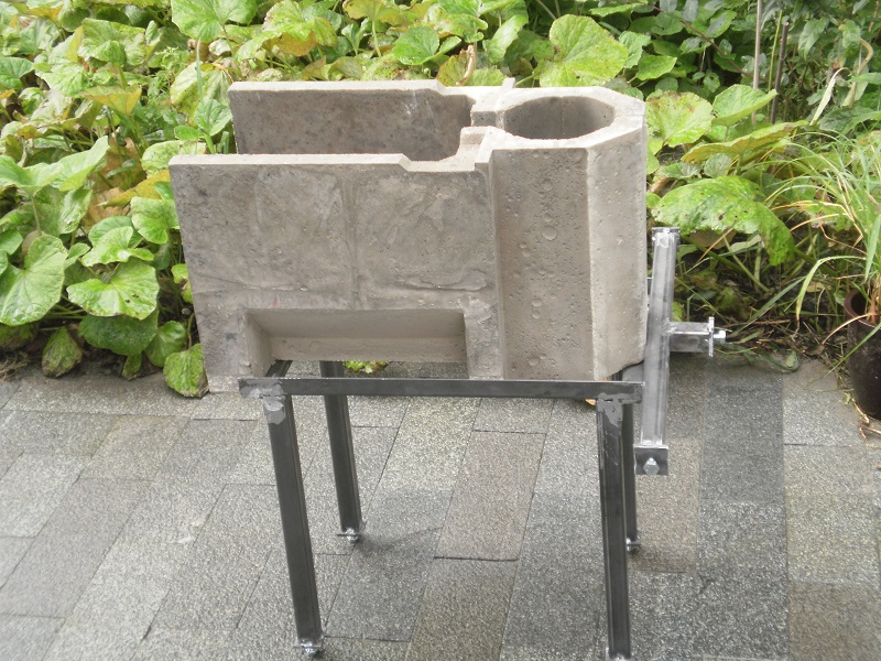
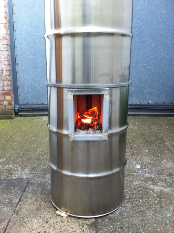
3 butt batch rocket
During winter of 2013/2014 this heater functioned equally the focal indicate of my old workshop. It is built as a 150 mm (6") riser bore system, the same size as the chimney pipe. The whole of the oestrus extractor side consists of three barrels on summit of each other, forming together a single cylinder. The top and bottom chapeau of the middle barrel are both cut out. The lower butt is open at the top and the top 1 is open at the bottom. Leave about 25 mm (1") around the perimeter when cutting out the lids, the added strength keeps the barrels circular. The batch rocket combustion core is a cast item which is protruding out of the side of the barrel cylinder. Run across the diagram below.
The masonry cavalcade in the lower butt is resting directly on the floor, it doesn't residual on the bottom of the barrel. A square opening in the bottom cut for the size of the cavalcade allows that to happen. A flange is bent and hammered on all four sides of the opening, leaving a gap betwixt the brick and steel which is stuffed with superwool to seal it off. This way, both the barrel and the column rest on the flooring independently. Another opening is cutting out and flanged to allow the cadre to stick out.
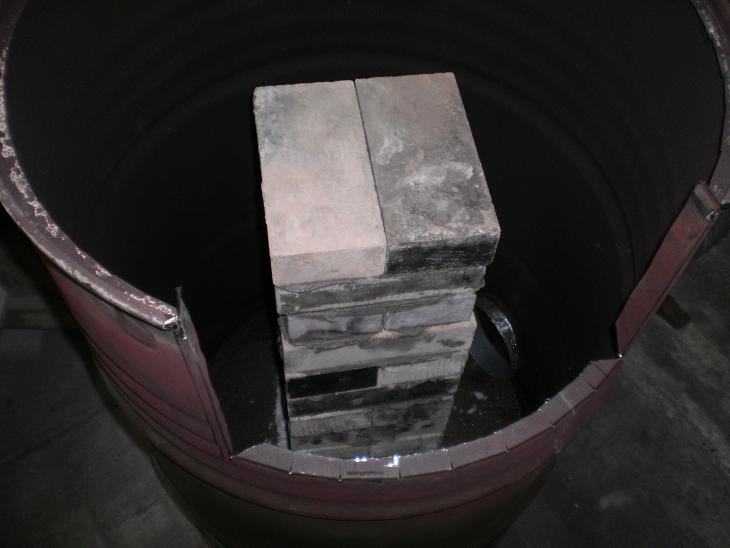
The core doesn't residual straight on the bottom flange, the internal masonry cavalcade and the external masonry support (come across diagram only above) are sized so that the cast core is elevated virtually eight mm (0.315") above the flange. A strip of superwool is glued (heat resistant stove caulk) to the flange which provides the seal. The riser isn't located exactly in the center of the barrel so the firebox isn't protruding out as much.
The gaps between the side of the firebox and the flanges are stuffed with superwool besides, equally is clearly visible. At that place'due south another cut out in the 2nd butt plus a small one to give room for the p-channel. Flanges are bent/hammered all around and the gaps filled with the same sealant.
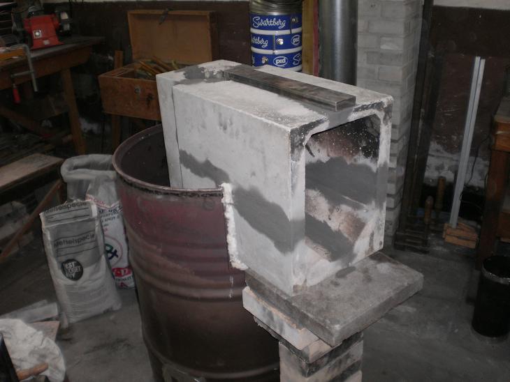
Next stride is the placement of the riser, I don't have a picture of this, regrettably. A vacuum formed superwool duct, mutual in the metallurgic industry, is used equally the riser in this heater. In the manufacture this blazon of duct is used to cascade molten metallic through to make full molds. Google "riser sleeve" or use this link.
The final step is preparing and placing of the tertiary butt. The rims are sealed with aluminum record, this won't concluding forever simply it is in full view so it's visible and easy to replace once information technology is worn out. The gas period internally does non hit the rims of the butt equally such, the one inch effectually the rim that was left when the top and/or lesser of the barrels were removed causes the hot gas to bend around them and so the rims where the aluminium record is used to seal the barrels always remain several tens of degrees libation than the remainder of the barrel.
The piping hot gases are spewn upward in the cylinder and need to go down to get to the only exhaust opening close to the floor. This exhaust is situated even lower than the firebox itself, which is around 500 mm (ane'8"). As such, this barrel tower is acting like a bell heat exchanger equally described in the "Bell theory" article. In addition to it acting like a larger bell due to the peak of the combustion core, information technology makes for very easy and less streneous feeding of the fire than having to bend down and kneel to put the wood in.
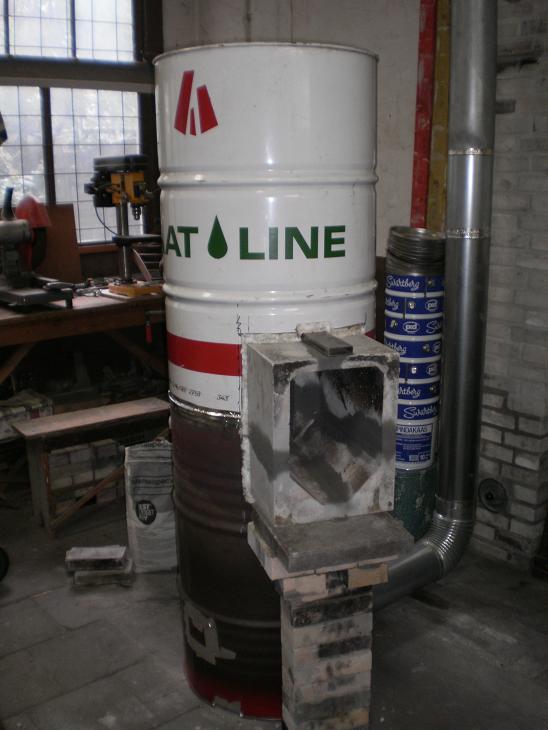
To foreclose having a restriction for the gases to access the frazzle opening (a common fault and ane of the get-go points to cheque in a poorly performing heater) the pipage is mounted virtually 100 mm (4") from the floor. Making a larger hole of 200 mm (eight") is another way to aid avoid whatever restrictions. In combination with a 200 to 150 mm (viii" to six") reducer to the diameter of the chimney pipe.
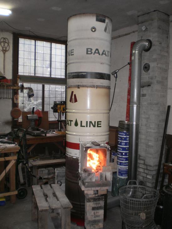
During the top of the burn the temperature of the uppermost barrel can easily reach 200 ºC (392 ºF) in this situation. So it would exist sensible to go on combustible materials well away from the heater. Indeed when constructed in this fashion treat it equally a "normal combustion heater" and apply whatsoever and all codes applicable to the installation of such metal boxes.
I did non ever get effectually to making a door for this variant, a split up canvass of Robax rut resistant glass is used instead plus a couple of firebricks to shape the air inlet. Of course a door can exist made if then desired. The chimney stack is direct, uninsulated masonry and viii.five m (27.9') high, measured from the point where the pipe is inserted through the brickwork. Hither is a low quality video showing in steps the burn's progress.
And final only not least: the report on the Rocket Stoves Forum dating from October 2013 about this subject area.
No 3D drawing avaiable, sorry.
Dorsum to peak
Bell with dead-end benches
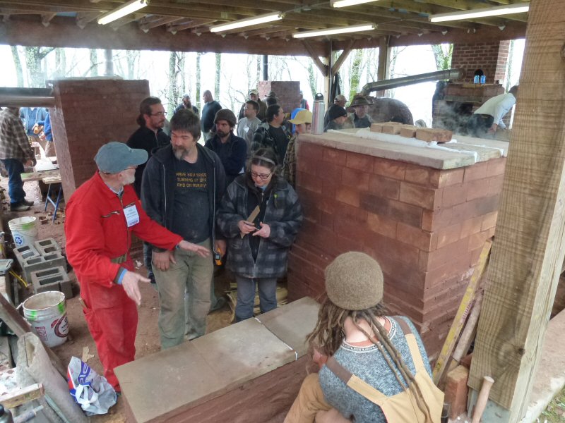
This mass heater was congenital during the 2022 Annual Meeting of members and interested parties of the Masonry Heater Association of North America. This organisation of heater masons invests a lot of endeavour in making clear to governmental parties that their heaters are among the cleanest in the United States and Canada. Other activities are educating the members and providing standard designs, so in that respect they embrace the open source ideal shared past this website.
The chief bell is drawn equally a double peel blueprint just during the (6!) workshops plus several mini-clinics and demonstration projects information technology turned out that the fire bricks were in short supply. In response to that problem the layout was altered to a consummate unmarried skin build, merely the pinnacle half of the main bell was built out of burn brick in order to cope with the expected high temperatures. In Due north America, usually the masonry heaters are built as double skin, the inner pare entirely out of fire bricks. We skipped that layout during this workshop, the goal was to demonstrate a proof of concept for the MHA members, a bell rut extractor married to a batch box rocket core. Information technology turned out to be quite a success, the thing burned really clean and the benches heated up without a hiccup, right out of the box so to speak.
A vacuum formed superwool cylinder of 200 mm (eight") diameter was used for a riser, the benches are drawn as unmarried skin and the main bell double skin. A number of the MHA members found it strange the benches were built as dead ends in opposite directions. Doing it this way, it would exist impossible for the frazzle gases to stream through in one, let solitary both of them. The next picture shows the heater during the curing stage, the steam is coming off as lazy clouds. The top of the pictured bench already shows lighter spots. The end of the demote is still wet being completed last, less than an hr before lighting first fire.
In that location are a few tricks in this construction in order to become the hot gases to enter the benches, stream forth the acme of the benches and cool, and make their way dorsum to the chief bell to the exit located at the bottom. This mechanism relies on a principle of physics, the fact that hot gases are lighter because they accept expanded. This is called the buoyancy of gases, driven past gravity and is the mode a bell system works. Hot gases tend to ascension and colder gases descend, to the exit. See alsoBell Theory.
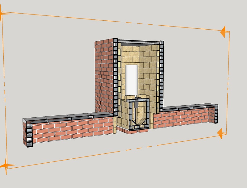
From this cutting-away it can exist seen that the opening between the main bell and the benches have no obstructions, the interior of the bench is carried through straight into the bong itself. In fact, this means that the benches are actually simply a continuation of the bell and grade a single, larger bell with estrus distribution sculpted to satisfy a new set up of demands. Another illustration of the versatility of the bell concept. As covered in the Bell theory section, nosotros can encounter that every bit the gases enter from the bong into the benches they enter a *much larger book* and so slow down greatly, rise to the top, shed heat and make their way to the exit.
So there'southward a lot more time to transfer its heat. Naturally the primary bell is the get-go to receive the gases, indeed the hottest gases, and so is the first to rut up. They then cool and make their style to the benches. So information technology is to be expected that the bench warms up subsequently the bell, and in this structure that fourth dimension delay was merely 20 minutes. If the bong had been fabricated of a double skin of bricks co-ordinate to the drawing, then the benches would take been the first to warm.
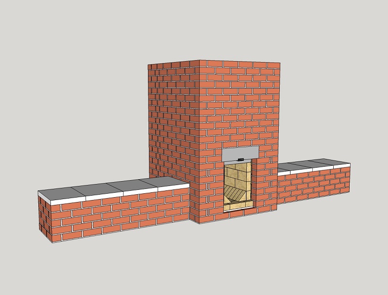
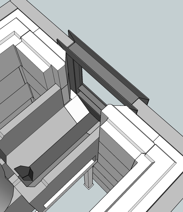
The placement of the exhaust opening to the chimney stack is very important in this pattern, as in any bong design. Equally this blueprint has benches attached to it (absent from the previous examples shown) thought needs to be given to how we get the hot gases into the benches and not 'short circuit to the get out flue' beforehand. The drawing below shows how it was achieved. A fireproof baffle board (in this case calcium silicate) is placed off the rear wall of the principal bell and capped off at the superlative, meet 3D drawing how this is done. Not seen in the picture below is the get out flue, 'hidden' behind the baffle plate. The circumference of this bamboozle board multiplied by the altitude between information technology and the rear wall of the bong should exist much larger than the cross sectional area of the flue. This is to ensure nosotros do not have a restriction to the easy flow of gases into the flue. The openings cut into the baffle (as seen below) are too of a size much larger in area than the cross section of the flue. Again, nosotros do not want restrictions to the gases. There is no 'opening' at the tiptop of the baffle board, we exercise not want access to the exit flue until after they have opened into the benches. Note that the cutouts in the baffle are well beneath the level of the benches.
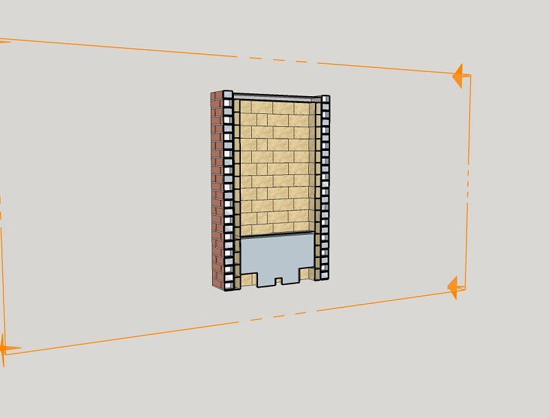
This baffle plate has helped us to achieve all nosotros want from a bong. Every bit the gases can ONLY attain the leave flue by entering behind the baffle plate from the bottom, merely the coldest gases escape. To reach that opening the gases must have had to enter the benches and cool. Nosotros can also now run into how "expressionless end benches" that initially baffled some of the attendees are and then effective. It should also be articulate that a bamboozle lath is non the merely solution, information technology happened to be the quickest and easiest style to practise it during a "time starved" week. All that is needed is that the gases reach and warm the benches before exiting the flue, so it could be done with a shallow and wide opening at the bottom of the rear wall of the bell which leads to the vertical stack by means of a funnel shaped brickwork.
Big N American masonry heaters unremarkably have a "bypass valve" incorporated. This is a steel or cast fe plate which is mounted in such a place in the heater that when it is opened by turning or sliding out, the hot exhaust gases are allowed to enter the chimney directly by a shortcut. This is a way to heat up the chimney stack before the masonry mass is warmed upwardly and so the chimney draw is initiated beforehand. Its main drawback is it complicates the structure and introduces a weak part in the heater which shouldn't exist there in my opinion.
Still, it tin exist very handy when a cold heater needs to be lit in the depth of winter in an icy common cold house. When i thinks such a featherbed is desirable in this blueprint, such a valve could be mounted in the area of the baffle lath. Preferably not at the top of the bong which is the hottest area where a steel bypass valve could go warped or destroyed in time. The bypass valve shouldn't exist confused with a 100% closing flue damper which can be very dangerous when there are notwithstanding some glowing coals under the ash. Carbon monoxide can't be seen or smelled and it will kill people in their sleep when leaked into the firm. A 100% closing door is a much meliorate culling and in add-on to that, a CO detector is actually an indispensable safety mensurate.
The MHA meeting was a memorable upshot, with a couple of prominent names participating in the Rocket Heater team. Lasse Holmes, the creator of the batch rocket thought, Leslie Jackson, co-author of the "Rocket Mass Heaters" volume and Kirk "Donkey" Mobert, creator of the kickoff dedicated Rocket Mass Heater Forum. The photo below shows Lasse and Leslie dancing in front of the heater (or around the burn?). Just as an aside, the batch rocket heater hither produces less smoke than can be seen in the motion-picture show.
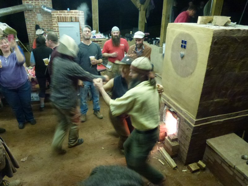
The two activeness pictures are copyright MHA, for more pictures commented by MHA'south Norbert Senf and myself see the photo report of the MHA of this workshop. The 3D drawing of the consummate heater is bachelor through this link.
Back to top
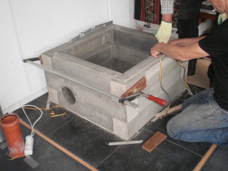
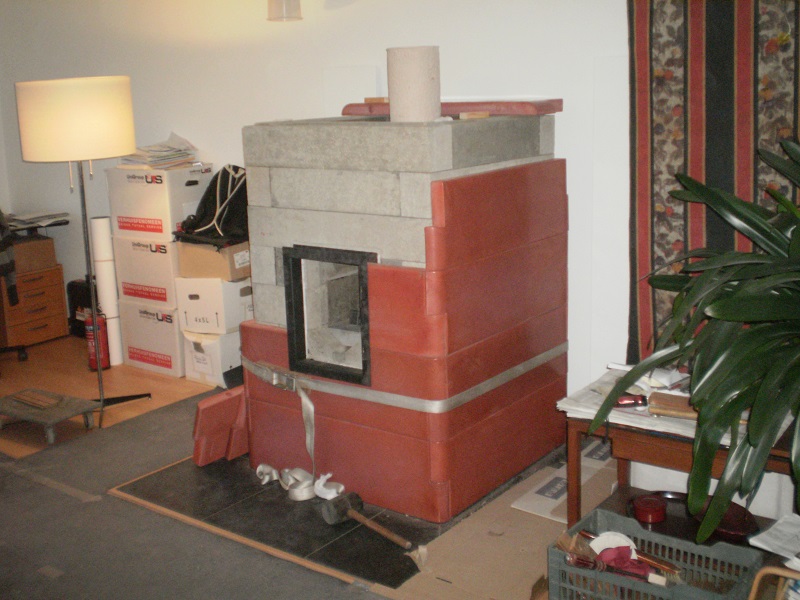
Bell heater entirely of cast parts
This is a batch rocket variant designed and congenital in 2015, consisting entirely of cast refractory parts. In such a project the financial investment in molds is very loftier. Then much idea was put into devising a way to utilise equally few unique parts every bit possible, thereby cutting down on the number of unique molds. As can be seen at that place are only a few parts repeated many times, the same few molds being used over and over equally required. The finished external dimensions of the heater are 98 ten 98 x 210 cm (3.22" x 3.22" 10 82.7"), and all up information technology weighs in at a little more than 2000 kg (two.2 U.s. tons).
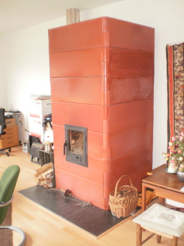
The outer finished face up is made of specially ordered castable refractory in a terracotta colour, and consists of 28 identical parts which interlock with each other (for those counting in the picture- a expert way to conceptually grasp information technology, the last 7 pieces form the rear wall behind, in other words four walls of 7 pieces each). The interlocking dovetails are seen at the corners, showing how the use of the same shape placed 'up and downward' alternately manage to interlock with each other.
An added do good of interlocking shapes like this is that it makes the construction easier as each slice is an easily handled and assembled part. A shut look at the dovetails in the picture shows the slight, but of import, angle they are cast at. This ensures that they lock together tightly, indeed force the dovetails to shut. Not seen are "ball and dimple" locating pins that locate and secure each layer to the other layer. Knowing that, and referring to the moving-picture show it is articulate that each layer is locked together as a unit past the wedge activity of the dovetails, and each separate layer is locked to the adjacent by the "ball and dimple" pins. All this allows gravity to do the job of holding it all together, they are not glued, mortared or fastened in any style. For full and complete details see the SketchUp cartoon of this project, there'southward a link provided at the end of this article.
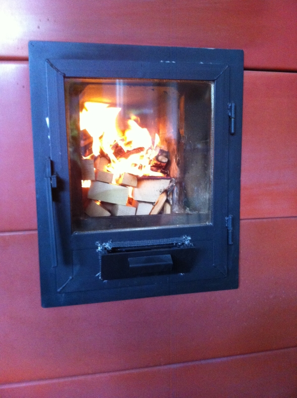
The door is made of steel T-profiles and hinges in a frame made of steel U-profiles with the open side facing outwards all around. That allows the outer skin pieces to fit into the open U which then supports and locks the door frame into place. (This tin can be seen more conspicuously in another photograph below.) A elementary tilting valve without hinges is mounted in the door which provides for the primary as well as the secondary air supply.
The firebox is identical to the description of "4: Cast core" in the affiliate "Designs" and consists of 3 separate and different parts. The lesser left and right parts together form the port and base of the riser and the third part completes the combustion sleeping accommodation when placed on the bottom pair. Meet assembled construction pic subsequently. The top office locks into the locating lugs seen beneath.
The core rests on a welded steel frame incorporating adjustable bolts in three directions to obtain right and secure placement inside the bell. This frame is also holding the left and right halves together by force of gravity (over again). Both halves are supported by the frame'south left and correct outer ridges just not in the middle. As a outcome, both parts have the trend to fall in each others' management and then the vertical seam will be held closed at all times. Note the steel frame doesn't support the core all of the style to the front, a small section of the core in unsupported past this frame. This will be explained after.
The upper office of the riser consists of a vacuum formed superwool circular tube which rests freely on the core base only held in place by a couple of brusk centering pins. Done in the most simple way: a couple of small-scale holes drilled in the refractory and a couple of shortened nails inserted.
The internal wall of the bell is built out of two different blocks, repeated 24 times each (naturally a slight modification to the exact duplication of these two parts occurs where the exit flue and firebox appear, other than that they are, similar the outer skin, a unproblematic repetition of parts). Note the natural language and groove seen in the pic, and careful inspection volition testify the tongue and groove exists at the ends of the pieces also.
One row consists of 4 parts and is 150 mm (5.ix") high and 120 mm (4.7") thick. Every row is turned a quarter horizontally relative to the previous one, thereby locking each other in place. The rows are sealed with adhesive braided drinking glass tape 10 mm wide and iv mm thick (0.39"ten 0.157") stuck to the natural language side. The weight of the parts volition press the seal downwards to one-half the original thickness. The same goes for the vertical ends, record on the tongue and force per unit area is applied to compress the tape and lower the role into place as the photo shows. Notation the groove is 2 mm deeper than the natural language is high, each block is resting on the sides, not on the tongue.
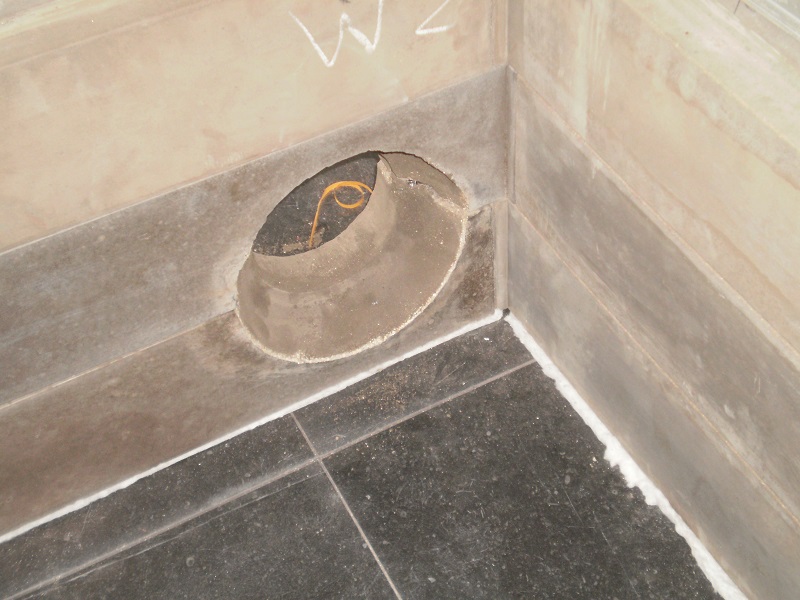
The exit hole to the chimney in this build is situated depression at the left rear side. Thanks to the fact that this is a bong structure information technology doesn't matter where at the perimeter the exhaust is placed. To avoid a restriction due to the placement close to the floor and the inner corner the hole is shaped as a funnel. The opening inside is 250 mm (10"), reducing to 150 mm (6") in the thickness of the material. This way, there's plenty of space for the frazzle gases to stream into the go out opening.
The size of the opening for the combustion chamber in the inner skin is determined by the inner dimensions of the firebox/combustion unit. The front of the firebox walls fits snugly in a rabbet of the inner peel. In this way, the front of the firebox is supported by the inner wall, the rear of the combustion core is supported by the adjustable metal frame pictured earlier. The perimeter of the firebox opening is sealed with superwool in the inner skin's rabbet/groove.
The left and correct sides of the inner skin'southward opening are chamfered at a 45 degrees angle in order to obtain infinite for a wider door and a ameliorate view of the fire. The particular about fixing the outer peel in the U shaped steel is clearly seen in the cartoon to a higher place and picture below. The next photo shows how the outer skin is assembled. At that place's also a superwool seal between the door frame and the inner skin, as is visible as a white line in the photo.
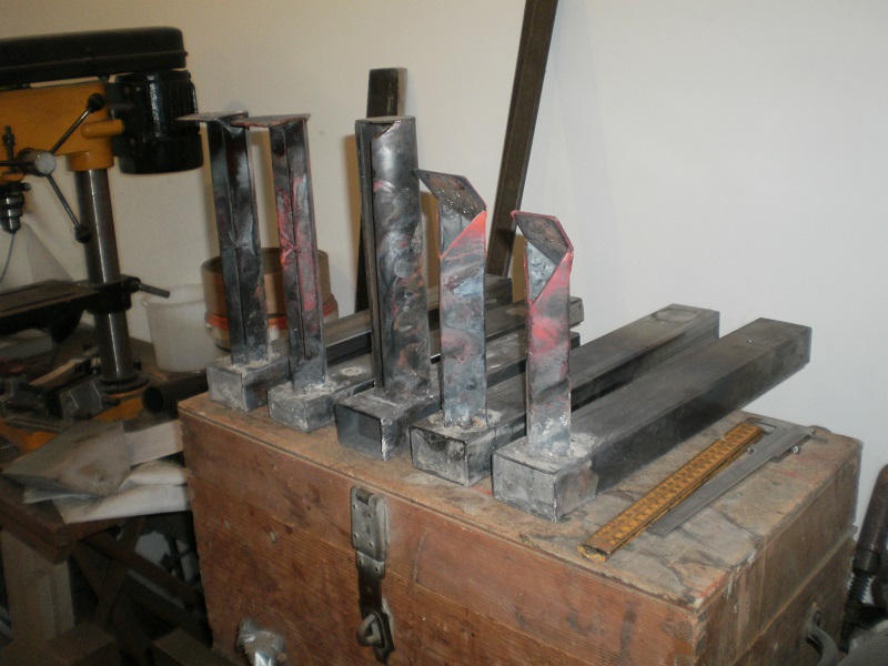
The configuration of the secondary air supply which generated the best results was found through a lot of experiments. Twelve different combinations were tested, variables such equally horizontal and vertical tube sizes along with the shapes and lengths of the air outlets were investigated. The next photo shows v of those combinations. All of those are affected by corrosion, some more than others. The model which will be in use in this detail heater is the second from right, the final version used has a slightly shorter vertical tube. The vertical function of the tube in the middle is a round tube and as such similar toMatt Walker's pre-port tube.
The secondary air supply (the floor channel) is fitted in a recess in the firebox floor, in fact the fire is on top of it. See the photo of the completed cadre if yous're unsure about where the floor aqueduct is situated. The primary air inlet (via the flap on the door) also as feeding the master fire besides feeds air into the secondary air aqueduct situated directly behind it. This primary air inlet besides is situated low in the door (see photo). As the temperature of the air inbound is very much lower than combustion bedroom surround it will naturally remain depression (cold air falls, in this case 'cold air stays low') and therefore the secondary air tube is fully supplied with air at all times.
The hotter the surroundings, the more than air is streaming into the floor channel. The duct itself is heated up past the burn which in plough pre-heats the incoming air. The triangle shaped opening at the top of the vertical role injects the air at halfway summit in the port.
At the front side of the combustion bedchamber a steel plate is mounted which diverts the rest of the air upward. Because of this provision the fire burns a flake more calmly and the chance to get a hefty CO-spike is reduced. Come across for this provision the relevant drawing in the"Designs" chapter.
For a temperate sea climate this is a large heater equipped with a surprisingly minor combustion chamber. With this pattern it is non needed to utilise "tricks" similar crisscross logs or "camp burn down manner" wood loading (used to lessen fume and help burning by incorporating lots of air in normal heaters). Such methods are not only no longer needed, but also lessen the load capacity. Just load the box, fuel laying forepart to back and it volition naturally accept enough air, acquired by the irregularities of the fuel.
Ane full load in this 150 mm (6") system size heater would weigh in at most six kg (13.ii lbs) bone dry out medium sized birch logs. The best results with this loading way and floor aqueduct every bit drawn will be obtained by a meridian down burn. When lit at the top of the whole batch as far back equally possible, a small kindling burn down will eat through the whole pile by itself.
Depending on the fuel size and the chimney depict the burn volition final between 55 and xc minutes. The chimney temperature, measured in the heart of the chimney pipe won't go higher than 80 ºCelsius (175 ºF) when the heater is started cold. When the heater is fired a couple of days in succession the highest temperature in the stove pipe will be around 120 ºCelsius (248 ºF). In that last case information technology is recommended to use larger bore fuel because the chimney depict volition exist quite a lot stronger.
All molds and castings, excluding the castings of the core, are fabricated to order by Bergkachel v.o.f. in The Hague, Netherlands. The 3D cartoon in SketchUp 2022 format of the complete blueprint is downloadable through this link.
Drawing updated ten/05/2016.
Back to top
Batchrocket central heating boiler
The design outlined here is made and built by Rémy Bakker, living in the north of Limburg, Netherlands. He lives in the vicinity of the Reichswald in Germany, his nickname is "Holtere", which is an one-time expression for "woodlot". The whole history of his heater(southward) are described in a thread on the Ecologieforum titled "Update bouw houtkachel". It'southward in Dutch only simply lots of pictures are included.
Note: the following is for illustrative purposes merely, a system as complex equally this should simply be undertaken by those competent to exercise so.
"Our heater is not centrally located in the house and we need quite a lot of estrus for the in-flooring heating of the rest of the business firm outside of the living room. In fact, the living room is thoroughly insulated and is a recently built annex to the 1920-ish house. A warm h2o appliance could be incorporated so this is how the pick for a central heating boiler was fabricated. Continued to a couple of big solar water heater collectors and a similar sized storage of chiliad liter (35 cu ft). The pump starts running when the water temperature in the exchangers is over 75 ºCelsius (167 ºF)."
Some figures:
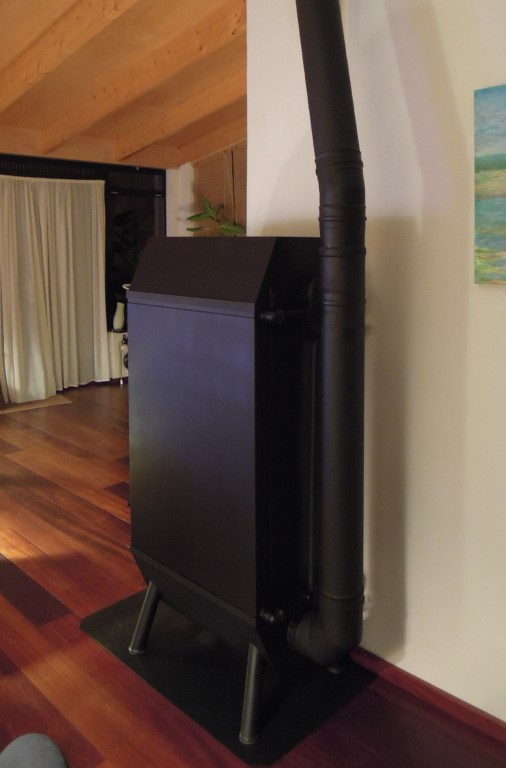
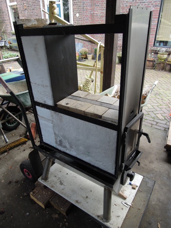
RBB wood heater for an unpressurized system.
Dimensions of the heater: Due west x D x H= 48 x 75 x 157 cm (1.57' ten 2.46' x 5.fifteen').
Systemsize of the RBB is 150 cm2 (23.3 sq.in.) or 138 mm (five.43") diameter, chimney connection 150 mm (6") diameter.
Internal size of the firebox: Westward ten H x D= 20 x xxx 10 50 cm (7.87" ten eleven.8"x xix.vii").
Maximum load 6 kg (13.2 lbs) beech per bike of 45 minutes.
Estrus release straight to the room estimated 2 to four kWh (6820 Btu up to 13600 Btu) maximum.
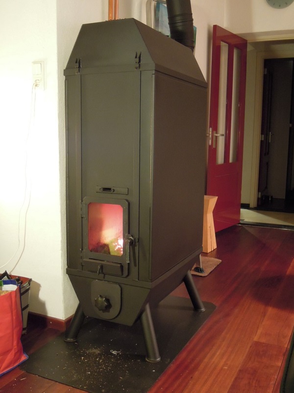
Externally, the sides become to between 60 and 75 ºCelsius (140 and 167 ºF), the same as the water temperature, the rear wall a bit warmer. The front end, together with the door becomes hotter, peculiarly the meridian half (maximum 180 ºC (356 ºF)). This could be lowered when the inside is insulated.
The heater is able to oestrus the 1000 liter (35 cu ft) water storage up to 75 ºCelsius (167 ºF). When the return temp rises past 75 degrees, firing should be reduced to preclude humid noises and for safety reasons. A manner to counter this effect is to overstate the exchangers, more volume ways it will take more time to become the water to boiling bespeak.

This could exist done by using fewer fire tubes and/or making the substitution panels wider. For example with 11 burn tubes instead of 12 similar in this implementation. The sides of the exchangers within the heater could be insulated. As it is now the water is heated up from two sides, from inside the heater in a higher place the firebox and inside the tubes.
Unpressurized systems are more prone to boiling noises as compared to pressurized systems where the humid temperature can be every bit high as 125 ºC (257 ºF). The large side panels of this heater are not designed to tolerate more than "normal" pressures, so this system operates at normal atmospheric pressure.
The lower part of the heater is made out of stainless steel because of condensation fluid, which is acidic and could cause corrosion. There'south no bleed for condensation fluid but this could exist done after.
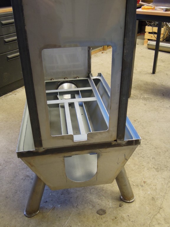
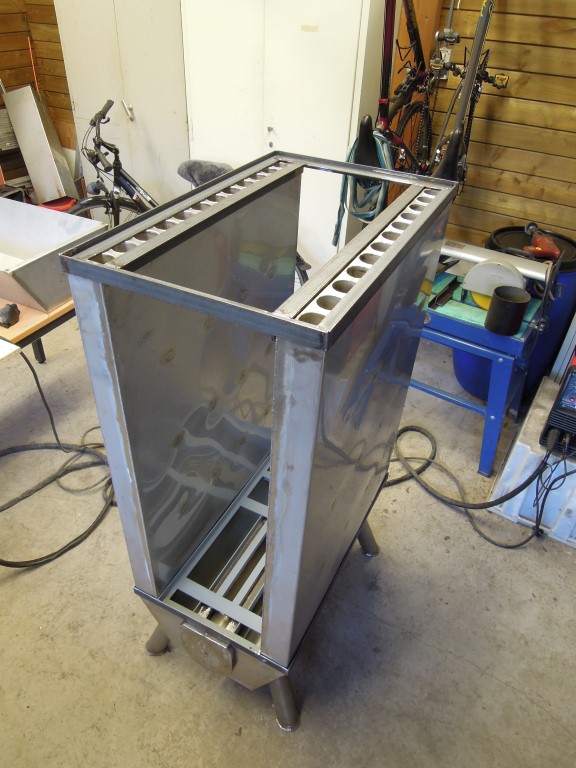
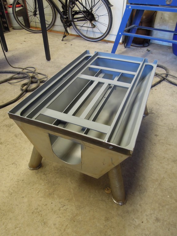
The frazzle gases are coming down through the exchangers on both sides of the ash drawer and stream to the back where the chimney pipage starts. The ash drawer hangs on a couple of track and is shorter than the depth of the heater. This way, there's always infinite plenty for the gases to stream to the go out hole. In this construction information technology isn't necessary to make the ash drawer airtight because in that location's a 2d p-channel on the slit in the floor of the firebox.
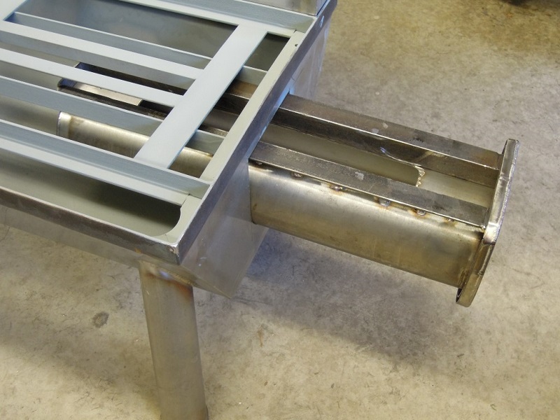
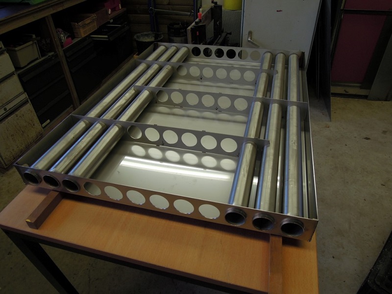
The size of the heat exchangers is 99 x 75 x 7.5 cm (39" x 29.five" x iii"). Each of them contains 12 fire tubes sized 48 mm diameter ten 2 mm thickness. At the bottom the tubes are sticking out slightly, to encourage condensation fluid to baste down. The frazzle gases of 900 ºC (1160 ºF) from the rocket core stream downwardly through the burn down tubes. The water, independent in the panel around the tubes streams from the bottom up. Internally, there are baffle plates that strength the water to take a more circuitous path on its way upward through the panel.
The elevation of the heater is double skinned with a infinite of xx mm (0.79") at the sides and xxx mm (1.18") at the height betwixt the skins. This space is completely filled with superwool to insulate the living space from the very hot within of the heater.
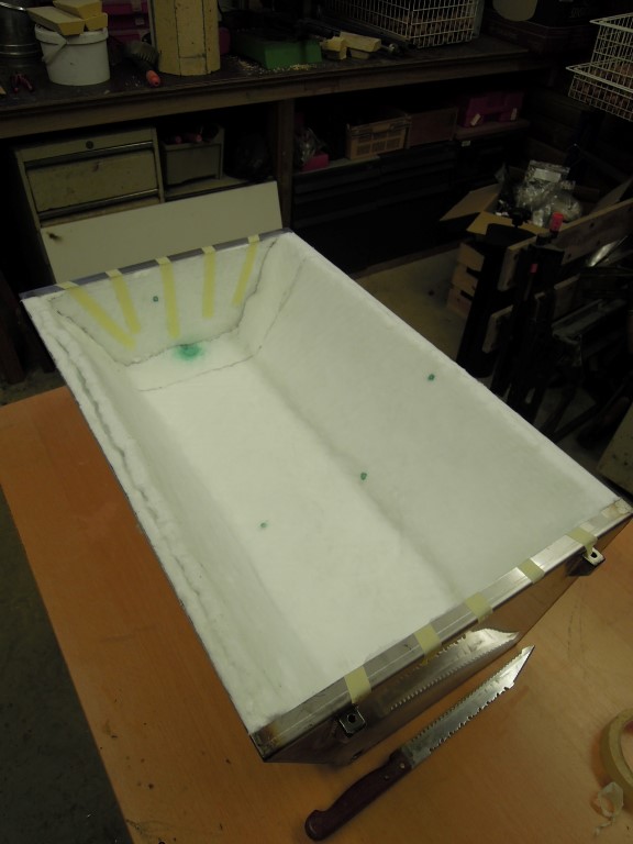
Pieces of vermiculite board are mounted directly to a higher place the riser to protect the steel from overheating. The temperature at the outside of the heater'due south summit is around 50 to 80 ºCelsius (120 to 175 ºF), more or less the same as the sides of the rut exchangers.
The riser is built of divide fire bricks of 30 mm (1 1/four"). All those are cutting to an bending of 67.5 degrees on both the longest sides, together they form an octagon riser.
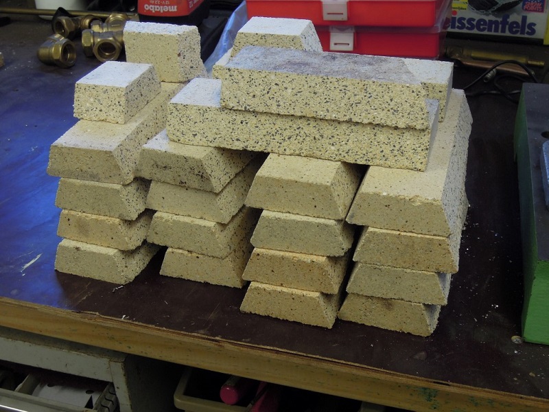
The riser parts are glued together with stove caulk and secured with welding wire. To help maintain strength the joints are staggered, and then achieving a running bond.
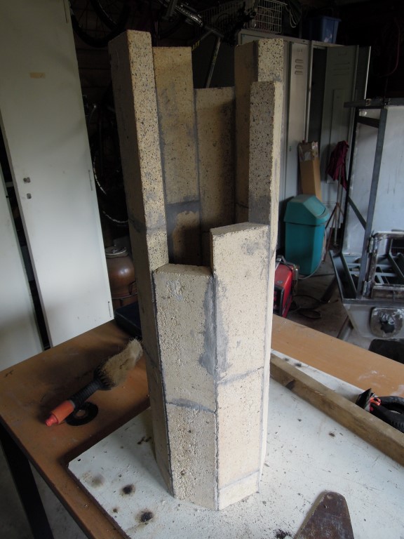
The riser equally a whole is secured and insulated with a mix of vermiculite and clay.
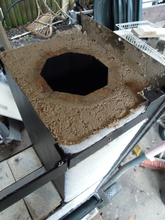
The firebox is congenital out of fire brick boards of 30 x xxx 10 4 cm (12" x 12" x 1.57").
The sides of the firebox are also insulated with a layer of superwool. This is done to prevent the firebox from losing too much heat to the exchangers. As always in rocket heaters we lose equally trivial heat as possible from the combustion itself which is an essential part of their efficient operation.
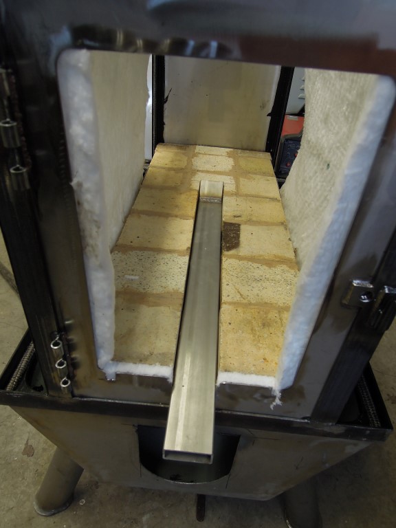
The picture above shows clearly the position of the second P-aqueduct. In a later stage it is clad with vermiculite lath, it serves every bit a chapeau on the ash drawer as well.
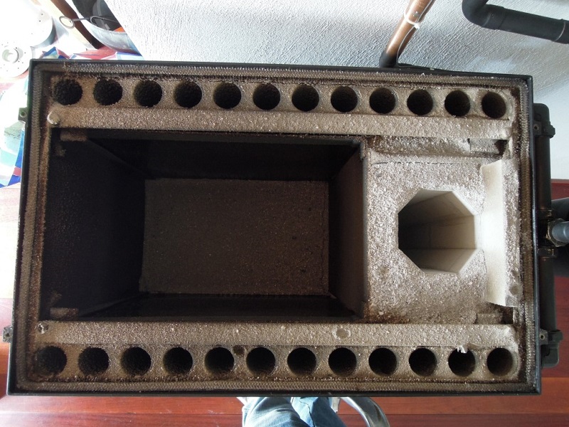
Exhaust gas temperature without turbulators betwixt eighty and 120 ºC (175 to 250 ºF), depending on the h2o temperature. As tin be conspicuously seen, later on the heating season the riser is completely white on the within and the fly ash on the exchangers is simply faintly brownish.
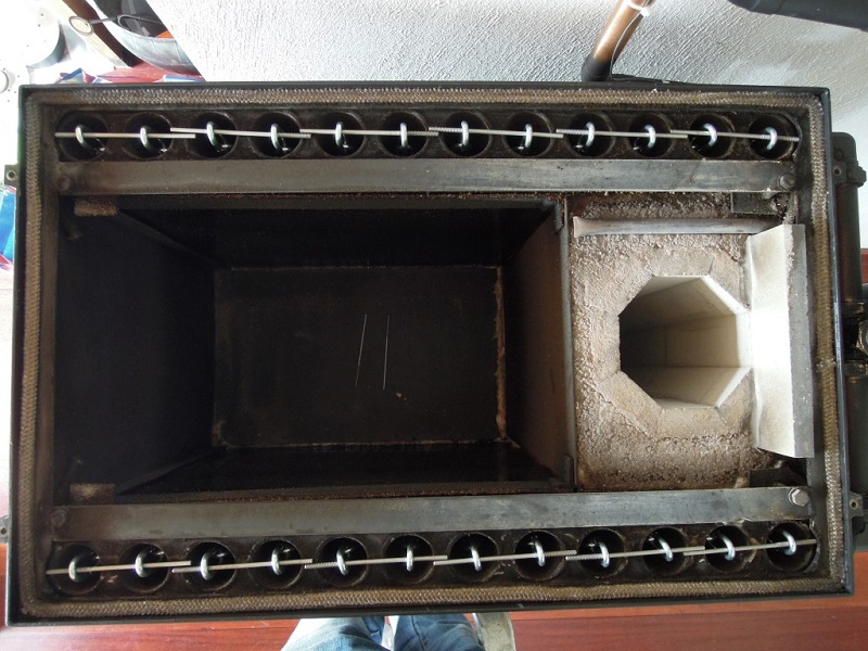
With turbulators (chains with 6 mm (0.25") links) the exhaust is the aforementioned as the water temperature, maximum 75 to 80 ºC (167 to 175 ºF) measured in the middle of the chimney pipe.
A drawing of the oestrus exchangers are available through this link.
Back to top
Pizza oven / terrace warmer / pool heater combination
The design outlined hither is made and congenital in 2022 by Tom De Smedt, living in Genk, Belgian Limburg. This commodity is very much the aforementioned as his thread at Donkey32'southward Rocket Stove Forum and included here with his permission.
Note: a organization equally circuitous as this should simply exist undertaken by those competent to practice so.
"After setting upwardly a pond pool in the garden, and finding out that there isn't much fun in keeping a cold puddle tidy that nobody's swimming in, I started playing with the thought to build a wood burning pool heater. Much and about examples on the internet, YouTube DIY versions equally well as commercial ones, seemed to be rather smokey contraptions, not to mention dangerous ones, and often plainly ugly. Then I stumbled upon the rocket stove engineering, and spent quite some time reading upwards, and thinking virtually how to use it in an aesthetically pleasing way.
I decided I was going to build a rocket powered puddle heater, just given the fact that information technology would be a fourth dimension consuming and rather beefy, not to mention plush project, I wanted to take a safety net, in case the pool heater didn't perform equally desired. This made me come with the thought to integrate a pizza oven with a swimming pool heater. When pool performance would be laughable, I could always continue enjoying the pizzaoven part.
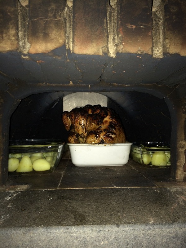
In the terminate, this resulted in the build I would similar to show yous all in this thread. It's proven to be capable of heating my 16000 liter (565 cu ft) pool from 20 to xxx °C (68 to 86 °F) in 24 hours of wood burning. I did the math, and this would hateful that on average, the heater is giving off ten kW to the puddle, which pleases me a great deal. During the building process, information technology has already served many a pizza, and a few roasted chickens as well.
Given the fact that my wife accepted it, I think it is adequately pleasing to the eye equally well, but I volition go out that judgement up to you. If anyone would like to endeavour the same, I hope they will notice inspiration in the post-obit pictures."
Stride one, foundations. Notation the pool pump in the background, substantially to the workings of the water heater.
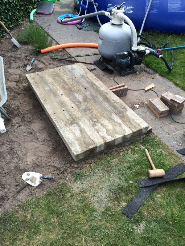
Step two, insulating the base with portland cement / vermiculite mix.
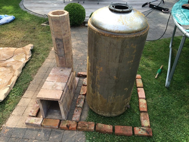
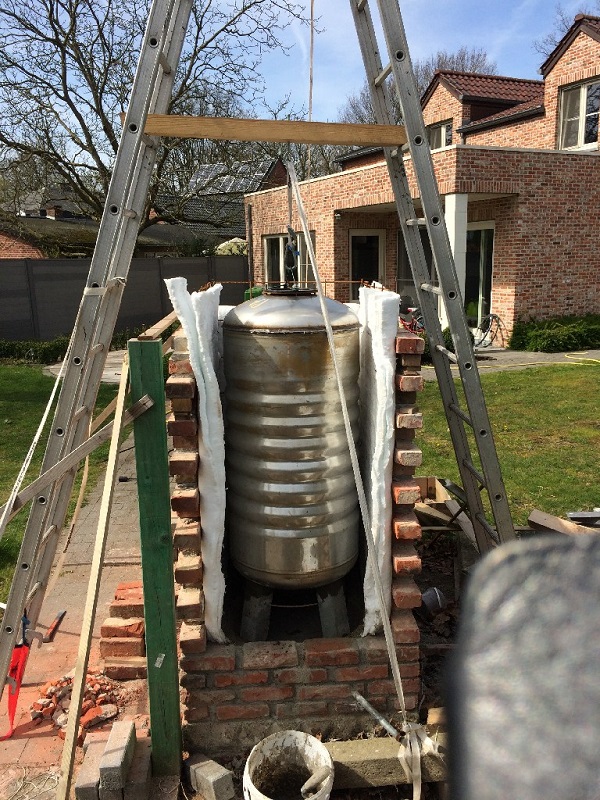
Step three, buying a second manus stainless steel boiler and cut split fire bricks into parts for a riser and a batch box. Note the final layout happened to be slightly different, in that the boiler is behind the riser.
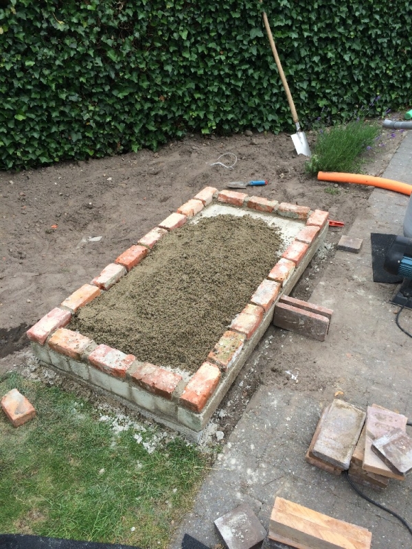
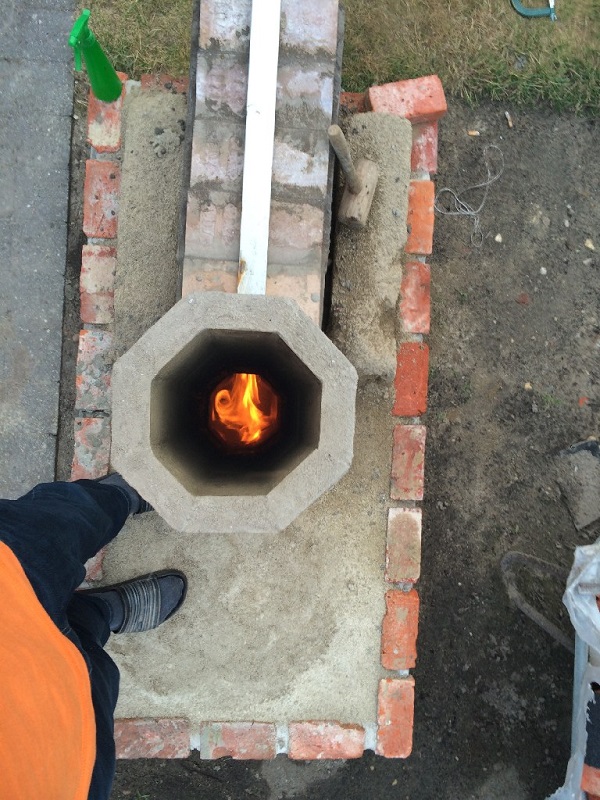
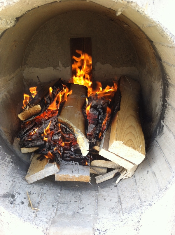
Footstep four, assembly of the batch box rocket on the foundation, using refractory mortar, and after curing, lighting it. => first success!
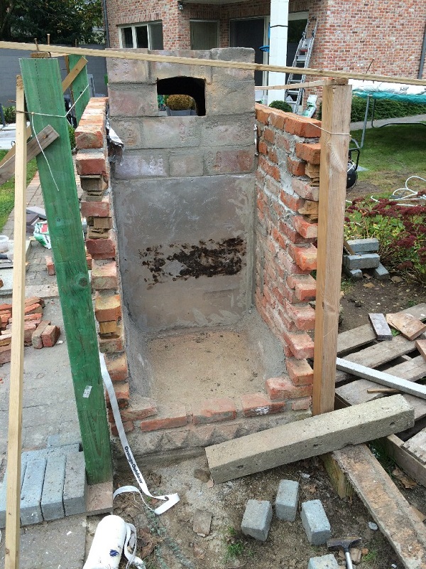
Step five, bricklaying and dividing into two compartments with a stainless steel plate.
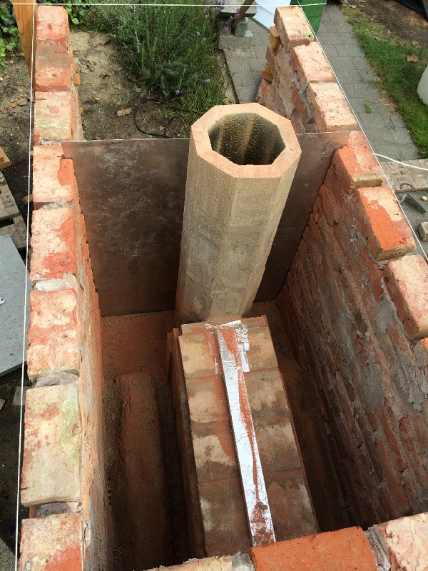
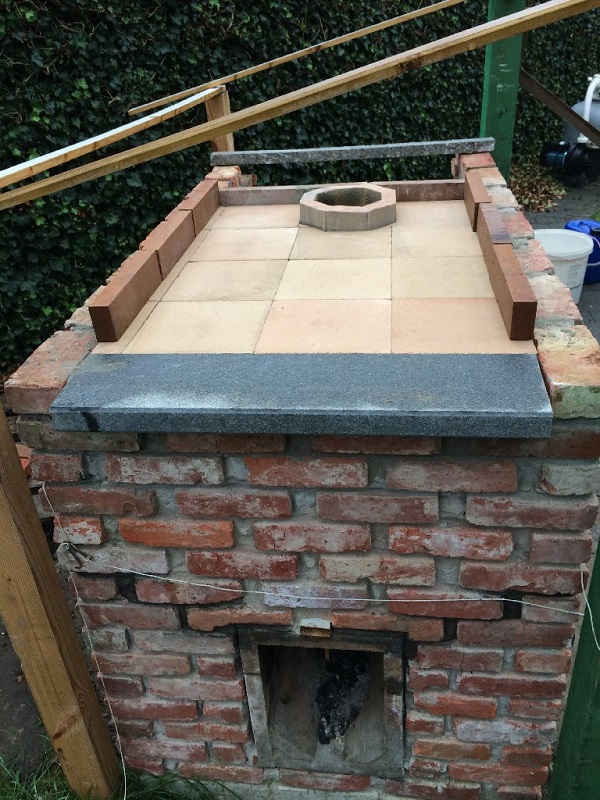
Step half-dozen, insulating the rocket stove with vermiculite and creating an oven floor with t-confined and 4 cm thick concrete slabs. T bars were given room for expansion. All in all, mayhap not the best technical option, simply wanted to keep footprint as minor every bit possible. The blackness soot on the backplate is from previous firings.
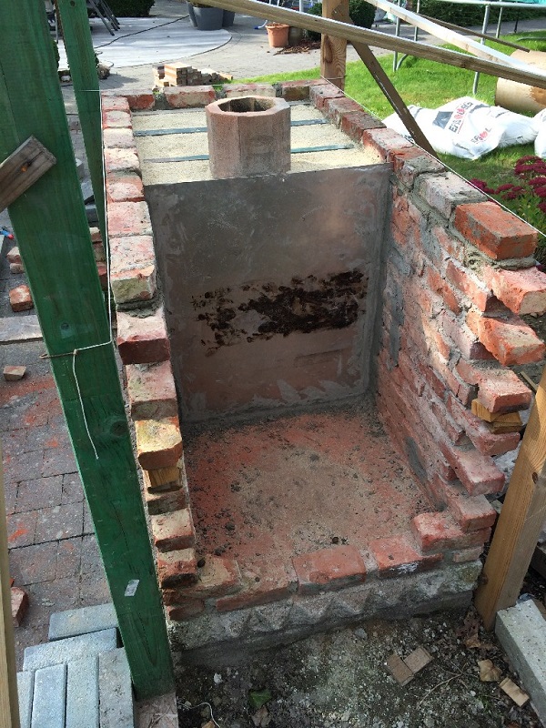
Stride 7, insulating the concrete slabs with vermiculite /portland cement mix, and laying refractory tiles. Not much space between the walls and the start of the dome, I know. (small footprint remember) I "insulated" that with 5 layers of aluminum foil, which in the end proved sort of satisfactory. The wall heats up to the point where you can't keep your mitt to it for more than than a few seconds, simply the good affair is that sitting beside the wall in the evening is rather cosy and comfortable.
Step eight, creating a mould for the dome, and building the dome.
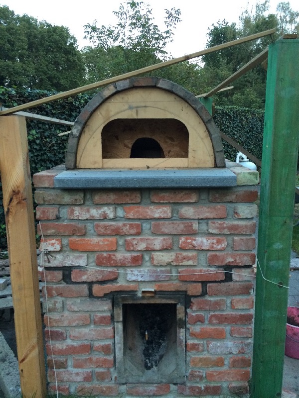
Footstep ix, taking away the mould, and cut and installing refractory forepart and rear walls.
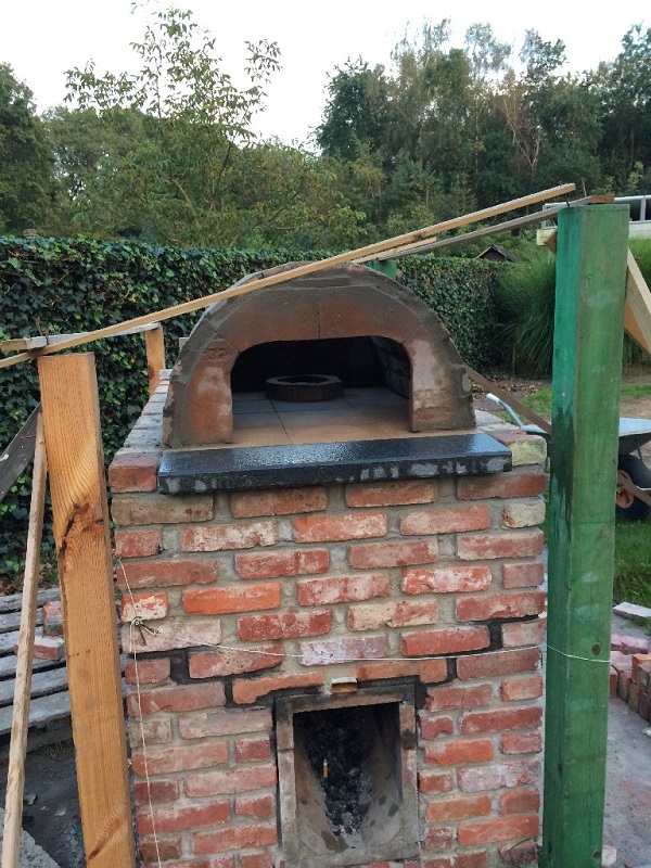
Step ten, bricklaying on a 2d mould, restarting over and over. Until in the end I had an curvation at the front and a closable opening in the back which has the same cantankerous section as the flue, 150 mm bore. The acme of the rear opening is flush with the oven ceiling, to minimize flue gas obstruction.
Step eleven, closing the opening with a brick and testing the oven. (beer in the butt chicken)
The oven stood in this phase for quite some time, until I could figure out how I would insulate the walls of the boiler compartment at a reasonable cost, and with good efficiency.
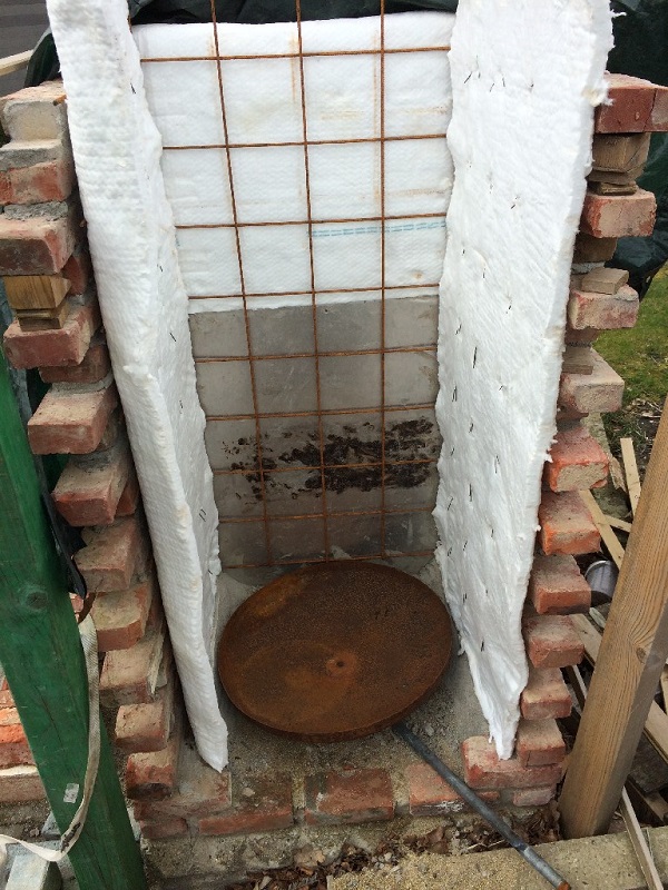
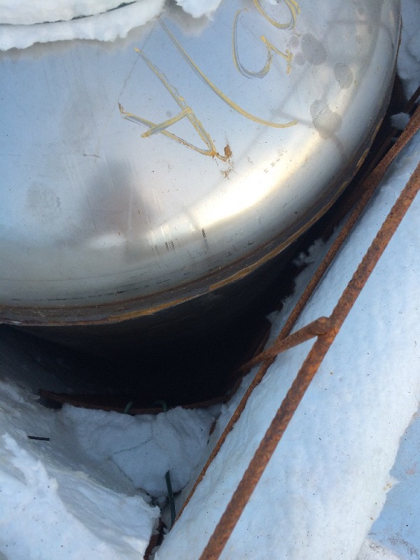
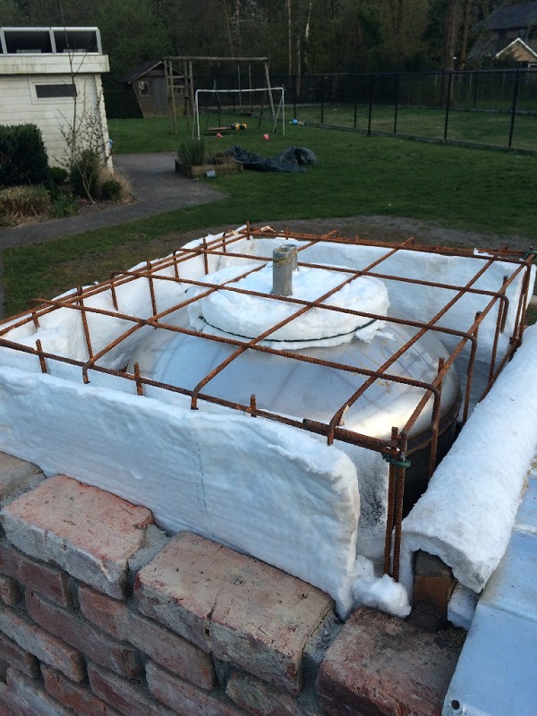
Step twelve, bought a ringlet of superwool, and created a skeleton I could necktie the insulation to and put effectually the boiler.
I too created a condensation fluid collecting tray from the bottom of the outer shell of the boiler, that I cutting off. The outer shell was not stainless steel, so I hesitated to use it for this purpose, but the metalworker who welded the pipe to it assured me that I would non see it rust to shreds any time presently. (of course stainless would have been the meliorate option anyway... fourth dimension will tell)
Stride thirteen, installing the boiler onto sort of a pedestal, so I would exist able to make clean out the ashes collecting in the tray.
Step fourteen, filling upward the edges of the compartment, to avoid shortcutting of hot flue gas to the frazzle. I used cutouts from the outer vanquish of the banality for this, and plugged it at the top with superwool.
(Editor's note: not really necessary, considering of the downward draft of the gases)
Step fifteen, closing off the top of the banality, keeping some headspace and insulating it. The longer pipe stub at the superlative of the banality is the cold water tube which is reaching down inside close to the bottom, the shorter one is for extracting the hot water close to the superlative. Between those, there'south a thermocoupler probe so the temperature of the water tin be monitored. Meet this small png how this looks like.
Footstep sixteen, closing up the rear and connecting stainless tubing and PVC puddle hoses, surrounding the acme with some extra aluminum foil for good measure.
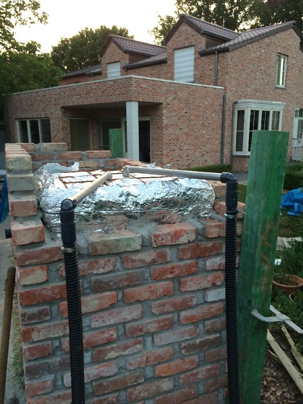
Step seventeen, I covered both the top of the dome and banality compartment with vermiculite / portland cement mix, to insulate and make it gas tight. So I bought and installed a second hand insulated stainless steel chimney, and bent some canvas metal and used some leftover insulation to produce two front covers for the oven and the batch box. Stainless steel handles were bought from IKEA.
That's where I'k now. I still need to cover the build with a stainless hat, or a bluestone slab, I'm undecided as of yet. I too have some grouting left to exercise.
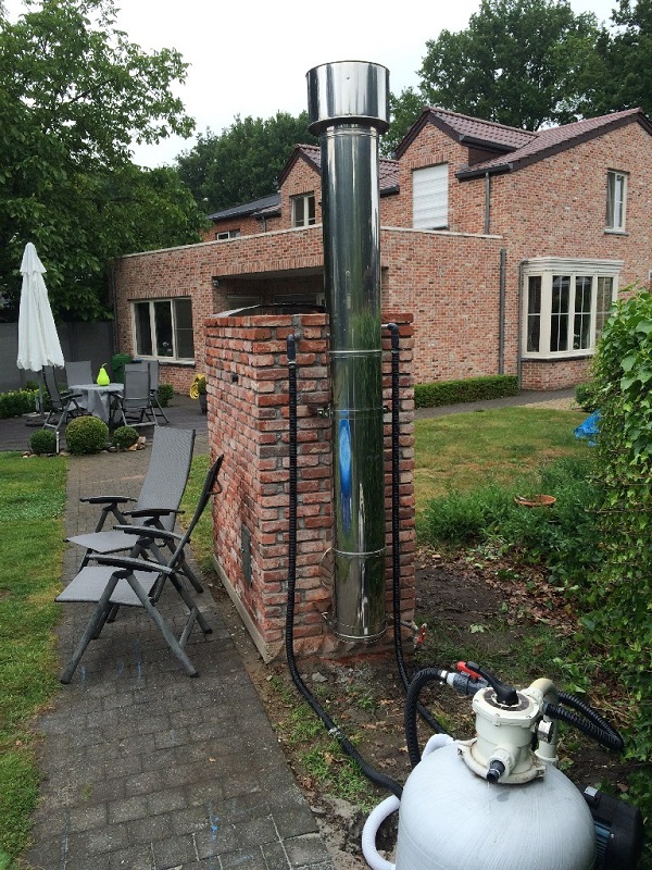
(In order to avoid rantings nearly the dangers of heating water with fire, and possible pressure buildup and and then on, I will mention that I consider this pattern equally safe, since the banality is continued to the pool and pump unit without any valves or obstructions. My pool filter pump is programmed to pump filtered h2o through the banality for fifteen minutes, every other fifteen minutes. In case the power fails, I can ever open up the pizza oven door, and close off the back window, to stop heating the water, and avoid melting my hoses with humid hot h2o. In the result of failure at least the boiler is exterior and not in a unsafe position equally it would be in a basement.)
Regarding oven temperature, I have no means of measuring it (all the same), but Sun evening June 25th 2015, the dome and oven floor were admittedly make clean, non a speck of soot, or spilled cheese remaining anywhere. I've been led to believe this starts to happen when the walls are between 370 and 400 ºC (698 and 752 ºF).
When I started cooking with the boiler installed, I did notice that the initial heat decreased more quickly than in the by firings, when the back window was airtight off. I guess that's non as well surprising, plus it's all relatively speaking, the 8th pizza was still fix in under 4 minutes :)
I should mention that, due to the heat, one crack formed in the outside brickwork during 1 of the outset firings. The fissure is slightly larger when the oven is hot, and reduces over again when the oven is cold. It doesn't seem to get any worse, then I guess it just ways information technology has created its ain expansion joint. Better design on my part might have avoided that. If I would redo this, I would not rest the T bars on the outer wall, but on an inner wall, non touching the outer skin.
Step eighteen, the brickwork was grouted effectually half of July 2022 and I fabricated a sloped, painted hardwood cover for the oven in gild to agree more with the theme of the house.
Effectually the batch rocket the insulation is loose vermiculite, in hindsight information technology would be better to stabilize this with a little fleck of portland cement or clay.
Back to height
Open systems, without door, p-channel or floor aqueduct
Between July 2022 and June 2022 I designed a number of open systems without a door (and hence) no provision for secondary air. Don't expect those systems to be comparable with closed systems efficiency-wise, the backlog air factor is much besides large for that. Although there's a strong indication that these heaters are just as make clean burning as their higher efficiency brothers.
Please be aware that a heater with no door isn't recommended inside a house. Due to the fact that in essence information technology is an open fireplace, information technology could spill smoke inside the living room. Also, no door means the heater can't be closed which could be dangerous while people are asleep. In case the burn down isn't completely out, mortiferous carbon monoxide could spill out of the heater due to weather condition changes for example.
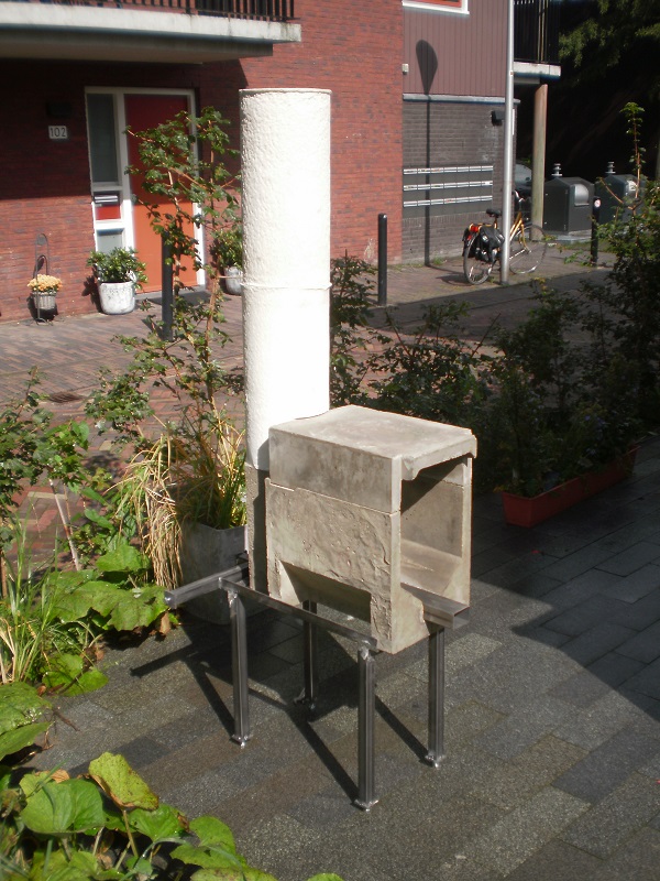
i: Münster, July 2017
The beginning open arrangement was mounted inside an art sculpture designed past Oscar Tuazon which was built at the same time during the decennialSculpture Projecte Münster of 2017. The term 'open up' has stuck when describing this organization. The concrete sculpture was built in the outside air aside a canal and meant as a space for people to hang out. With the possibility to light a fire in the firebox to warm upwards the concrete column. Which tin be very comfortable to lean confronting during dank evenings.
The firebox was a 250 mm system cast as a cylinder to match the hole in the concrete column and set horizontally behind the opening, the riser was cast with an octagonal cross section. The circular firebox' front opening had exactly the same cantankerous department area as the rectangular front opening of a 250 mm organization according to the recommended proportions. The riser in the picture appears to be very short, another piece of equal length was placed on top.
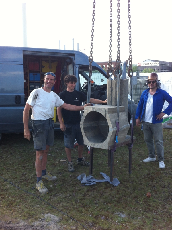
The physical cylinder being hollow with a closed tiptop served as a single bong of hefty weight, half-dozen metric tons. The chimney was mounted inside, starting twoscore cm higher up floor level and protruding merely 30 cm out of the bell's top (not visible in the picture). The riser had the normal back sweep (the ramp at the bottom rear of the riser).
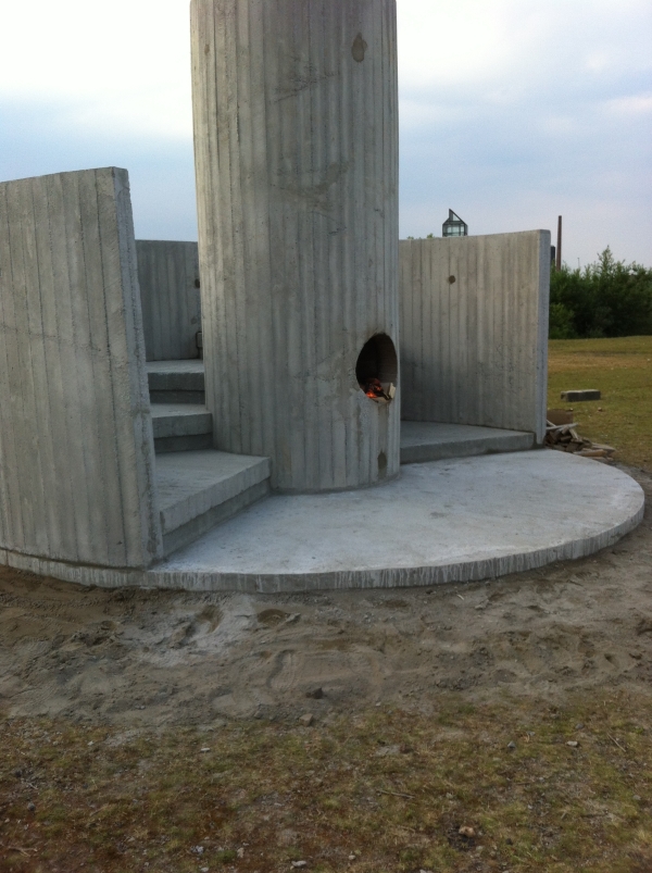
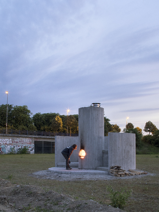
picture © Henning Rogge
Dorsum to top
2: Costless University, Brussels
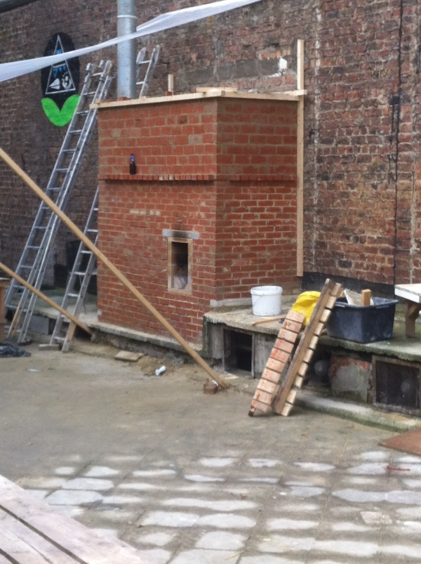
The 2nd open up system was built in the courtyard of the Costless University of Brussels (ULB) during April 2018, washed equally a workshop for and by the students. It was a brick 200 mm system ready inside one large brick bell. In outside air again, an inner courtyard on height of a parking garage. What makes this build interesting is that the back wall of the bell was actually an existing wall of a neighbouring building.
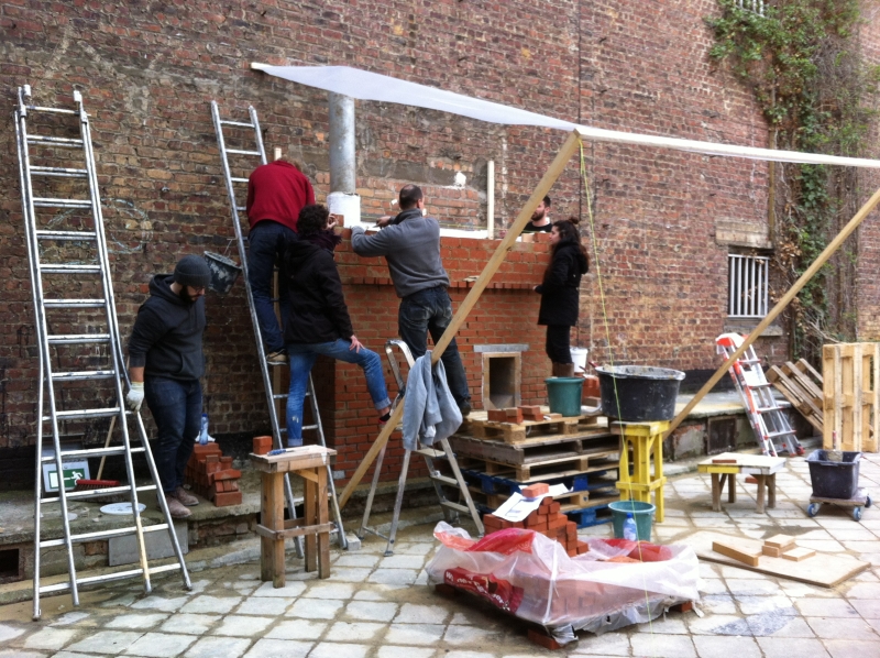
To preclude excessive loss of estrus into the large wall, the back wall of the bell is insulated with 25 mm of Superwool. Edifice the structure co-ordinate to the recommended values means that the bong is very spacious, even much more spacious than expected. The riser layout was done like the Mallorca build, square, out of divide fire bricks, no dorsum sweep, only the chamfered corners at the rear of the riser upwards to a level as loftier equally the port. Please read about the consequences of a square riser as opposed to a circular one in the"Building" chapter.
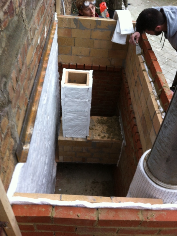
The results, although not tested with a gas analiser, were very encouraging. Information technology worked without too much persuasion simply one hour later on completing the build. In fact two ladies were notwithstanding doing pointing work while it was getting dark and the heater was fired upwards. A lot of water vapour came out the short chimney and after an hour this disappeared completely. The cartoon in Sketchup eight format can be obtained here:
The next morning a video was taken, sadly without the impressive depression rumbling sound that gives these heaters the name of Rocket Heaters.
Dorsum to top
iii: Maureen Paley, London
Another one was washed in the art gallery of Maureen Paley in London in June of 2018. Information technology consisted of two stainless steel barrels on top of each other and a combustion cadre congenital out of insulative refractory board.
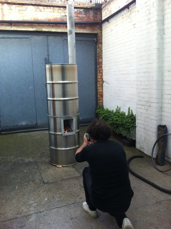
This heater is a arrangement size of 120 mm, so the riser is a square with 120 mm sides (with the remaining values taken from the tables for a size of 120mm). It's built within a partially open courtyard every bit an addition to the opening of the art exhibition called Burn! past Oscar Tuazon.
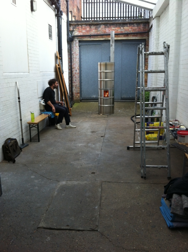
The flue is simply a directly pipe inside the barrels, starting almost 20 cm above floor level. Information technology performed very well although at the fourth dimension it could only be run with modest pieces of fuel. No further testing has been done on this one.
All three of the in a higher place projects were initiated by Antoine Rocca, docent of architecture at the Free University of Brussels (ULB).
Back to peak

colemanawasine1947.blogspot.com
Source: https://www.batchrocket.eu/en/applications
0 Response to "3d drawing of warm morning fire brick"
Post a Comment